The mechanical engineering department at Standard Fasel is able to analyse, design and calculate new and existing plant designs. As well as individual components and piping systems. With our years of experience in amongst others the petrochemical, food, energy, city heating and paper industry we are able to assist you with any problem or question you may have. The list below gives you a small insight in the things we are able to do at the engineering department at Standard Fasel.
Piping
We are able to design your complete piping system and perform stress and flexibility analysis on the newly designed piping systems and also on your existing piping systems. By using several state of the art software packages we can ensure that all designs are made according to the latest ASME, RToD and European codes.
Creating a Piping Specification
It is important that all your pipe lines are able to handle the fluid in the process conditions of your plant. For that we can make a Pipe Specification which includes the type of pipes and components that can be used for all the your pipe lines and processes. This standard can be used for different pipe lines in your plant.
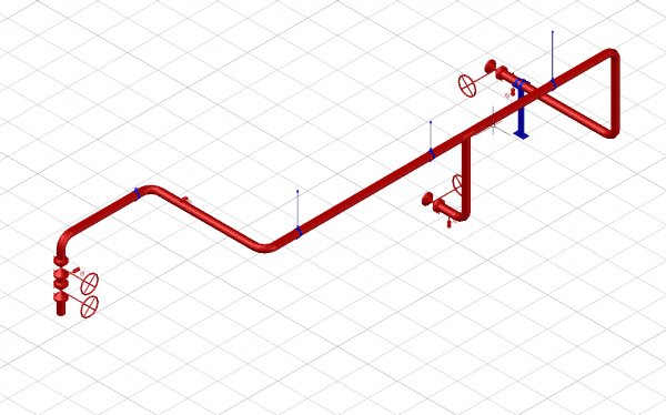
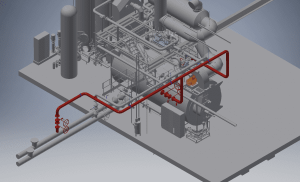
Creating a 3D-model of a pipe line
When you need a new pipe line or want a model of existing lines Standard Fasel can provide you with a 3D model in different CAD-formats. Depending on your needs the model can also contain pipe specs and tag numbers of the components (valves and instrumentation) included in the pipe line.
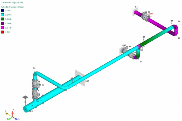
Pipe flexibility and stress calculations
To ensure that the pipe line is correctly supported we can make a flexibility and stress analysis of the designed piping system. This way we can ensure that your piping system will be able to cope with thermal expansion and external stresses acting upon the pipe line during its lifetime. When you are experiencing defects in your piping system we can also check if it is correctly supported and advice you on making the correct adjustments to prevent problems in the future.
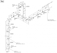
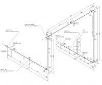
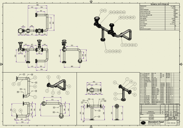
Creating production isometrics
Using our CAD-software we also produce isometric drawings that can be used for production purposes. This way we can deliver our pipe line with the complete documentation needed for the specified codes. The isometrics include a complete bill of materials (BOM) which makes it easy when materials are purchased. They also include weld numbers and process data, this way only one drawing is needed during ordering material fabrication and quality assurance.
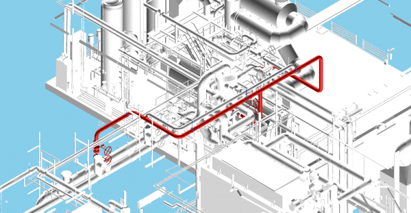
Plant layout
When a complete plant layout is needed we combine the outputs of the different CAD-systems and incorporate them into one 3D-model. When needed we also incorporate 3D-scans of existing plant layouts to make sure that the new components will align with the existing layout. This way clashes between pipelines or other components are easily detected and expensive adjustments in the field are avoided.
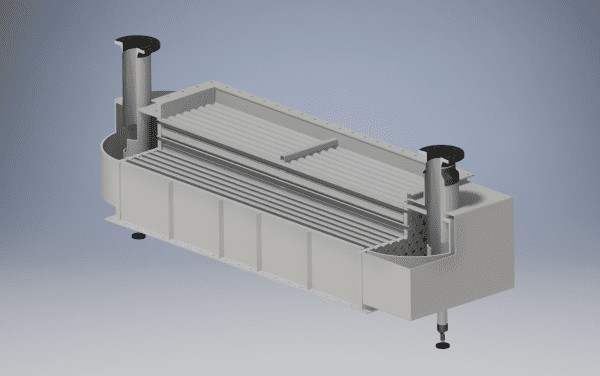
Vessels and heat exchangers
The engineers at Standard Fasel are able to design a new heat exchanger or vessel according to the latest ASME, RToD and European codes. With our years of experience in different industry branches such as Food and Pharma, Petrochemical, Energy, City heating and many more, we are able to engineer solutions to your specific needs.
Process calculations
The design process of new vessels and heat exchangers starts with gathering and analysing the available process data and the desired performance. By using different software packages such as HTRI, KED and Ansys we are able to accurately calculate the performance of each design layout. That way we are able to choose the design that meets the requirements the best.
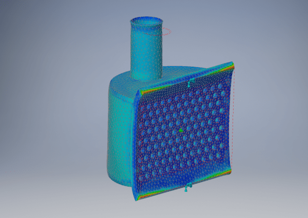
Stress calculations
Working with high pressures and high temperatures requires that stress calculations are made to get the design certified by the Notified Body (Nobo). Our stress engineers perform these calculations on all our designs and are able to do the same for you. A complete report is made that can be send to the appropriate NoBo. The calculations are done during the 3D-modelling stage. When errors in the designs are found during the calculations the appropriate action is taken by thickening the vessel walls or rearranging the nozzle pattern. Basic FEM simulations are also used during this stage.
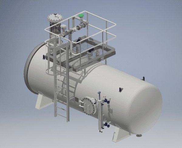
3D-modeling
With the design parameters calculated during the process calculation stage or gathered from an old drawing a 3D model is built with Autodesk Inventor. Combining the calculated parameters and stress calculations with years of experience guarantees that every design will perform at peak efficiency. Using the different tools of the packages we can check if the design can be made and if there are no interferences in the design and realisation.
Production drawings
When a design is finalised production drawings are made with the 3D model as a base point. Because the 2D-production drawings are directly linked to the 3D model errors are a thing of the past even when changes are made to the model. A bill of materials (BOM) is generated what makes ordering the components an easy task. We are able to provide you a complete drawing package, from the General Arrangement till the detail and production drawings. When needed the appropriate files are created for laser cutting or CNC-machines.
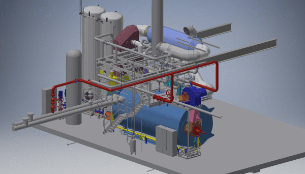
Plant layout
Combining the 3D-models with piping we are able to create a digital view of the plant installation. This all can also be combined with a 3D-scan making it possible for us give the client a tour through the plant in the virtual world.